The Raspberry Pi is one of the leading physical computing boards on the market. From hobbyists building DIY projects to students learning to program for the first time, people use the Raspberry Pi every day to interact with the world around them. Python comes built in on the Raspberry Pi, so you can take your skills and start building your own Raspberry Pi projects today.
In this tutorial, you’ll learn to:
- Set up a new Raspberry Pi
- Run Python on the Raspberry Pi using the Mu editor or remotely over SSH
- Read input from physical sensors connected to the Raspberry Pi
- Send output to external components using Python
- Create unique projects with Python on the Raspberry Pi
Let’s get started!
Free Download: Get a sample chapter from Python Tricks: The Book that shows you Python’s best practices with simple examples you can apply instantly to write more beautiful + Pythonic code.
Getting to Know the Raspberry Pi
The Raspberry Pi is a single-board computer developed by the Raspberry Pi Foundation, a UK-based charity organization. Originally designed to provide young people with an affordable computing option to learn how to program, it has developed a massive following in the maker and DIY communities because of its compact size, full Linux environment, and general-purpose input–output (GPIO) pins.
With all the features and capabilities that are packed into this small board, there’s no shortage of projects and use cases for the Raspberry Pi.
Some example projects include the following:
- Line-following robot
- Home weather station
- Retro gaming machine
- Real-time object detection camera
- Minecraft server
- Button-controlled music box
- Media center
- Remote experiments on the International Space Station
If you can think of a project that would benefit from having a credit card–sized computer attached to it, then someone has probably used a Raspberry Pi to do it. The Raspberry Pi is a fantastic way to bring your Python project ideas to life.
Raspberry Pi Board Overview
The Raspberry Pi comes in a variety of form factors for different use cases. In this tutorial, you’ll be looking at the most recent version, the Raspberry Pi 4.
Below is the board layout of the Raspberry Pi 4. While this layout is slightly different from previous models of the Raspberry Pi, most of the connections are the same. The setup described in the next section should be the same for both a Raspberry Pi 3 and a Raspberry Pi 4:
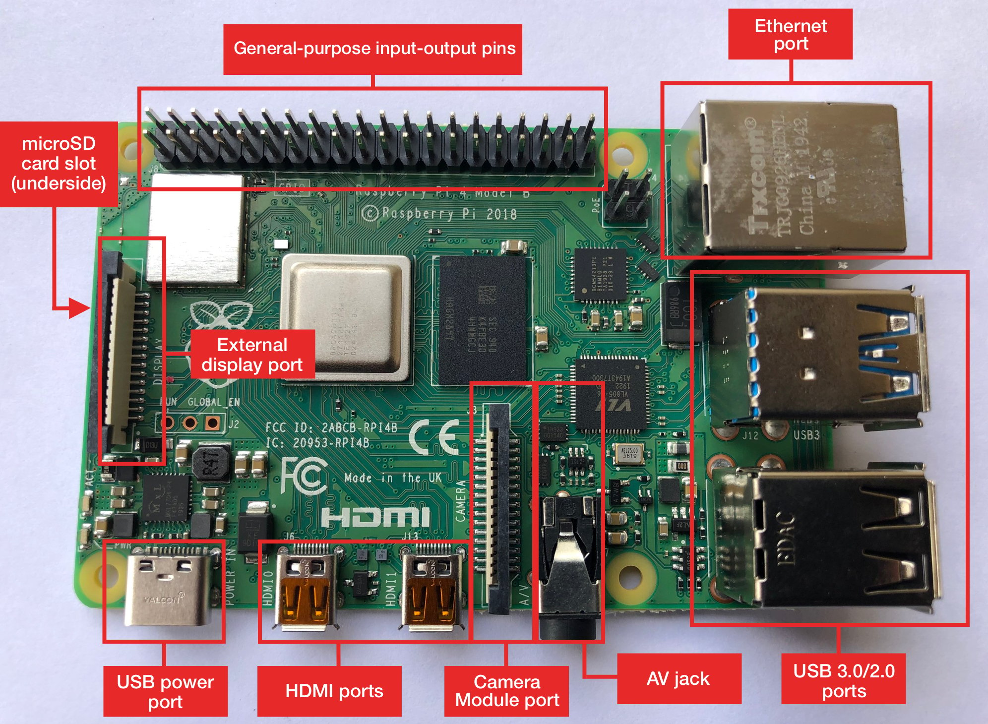
The Raspberry Pi 4 board contains the following components:
-
General-purpose input–output pins: These pins are used to connect the Raspberry Pi to electronic components.
-
Ethernet port: This port connects the Raspberry Pi to a wired network. The Raspberry Pi also has Wi-Fi and Bluetooth built in for wireless connections.
-
Two USB 3.0 and two USB 2.0 ports: These USB ports are used to connect peripherals like a keyboard or mouse. The two black ports are USB 2.0 and the two blue ports are USB 3.0.
-
AV jack: This AV jack allows you to connect speakers or headphones to the Raspberry Pi.
-
Camera Module port: This port is used to connect the official Raspberry Pi Camera Module, which enables the Raspberry Pi to capture images.
-
HDMI ports: These HDMI ports connect the Raspberry Pi to external monitors. The Raspberry Pi 4 features two micro HDMI ports, allowing it to drive two separate monitors at the same time.
-
USB power port: This USB port powers the Raspberry Pi. The Raspberry Pi 4 has a USB Type-C port, while older versions of the Pi have a micro-USB port.
-
External display port: This port is used to connect the official seven-inch Raspberry Pi touch display for touch-based input on the Raspberry Pi.
-
microSD card slot (underside of the board): This card slot is for the microSD card that contains the Raspberry Pi operating system and files.
A little later in this tutorial, you’ll use the components above to set up your Raspberry Pi.
Raspberry Pi vs Arduino
People often wonder what the difference is between a Raspberry Pi and an Arduino. The Arduino is another device that is widely used in physical computing. While there is some overlap in the capabilities of the Arduino and the Raspberry Pi, there are some distinct differences.
The Arduino platform provides a hardware and software interface for programming microcontrollers. A microcontroller is an integrated circuit that allows you to read input from and send output to electronic components. Arduino boards generally have limited memory, so they’re often used to repeatedly run a single program that interacts with electronics.
The Raspberry Pi is a general-purpose, Linux-based computer. It has a full operating system with a GUI interface that is capable of running many different programs at the same time.
The Raspberry Pi comes with a variety of software preinstalled, including a web browser, an office suite, a terminal, and even Minecraft. The Raspberry Pi also has built-in Wi-Fi and Bluetooth to connect to the Internet and external peripherals.
For running Python, the Raspberry Pi is often the better choice, as you get a full-fledged Python installation out of the box without any configuration.
Setting Up the Raspberry Pi
Unlike the Arduino, which requires only a USB cable and a computer to set up, the Raspberry Pi has more hardware requirements to get up and running. After the initial setup, though, some of these peripherals will no longer be required.
Required Hardware
The following hardware is required for the initial setup of your Raspberry Pi. If you end up connecting to your Raspberry Pi over SSH, which you’ll look at later in this tutorial, then some of the hardware below will not be needed after the initial setup.
Monitor
You’ll need a monitor during the initial setup and configuration of the operating system. If you’ll be using SSH to connect to your Raspberry Pi, then you won’t need the monitor after setup. Make sure your monitor has an HDMI input.
microSD Card
Raspberry Pi uses a microSD card to store the operating system and files. If you buy a Raspberry Pi kit, then it will contain a preformatted microSD card for you to use. If you buy a microSD card separately, then you’ll need to format it yourself. Look for a microSD card with at least 16GB of capacity.
Keyboard and Mouse
A USB keyboard and mouse are required during the initial setup of the Raspberry Pi. Once the setup is complete, you can switch to using Bluetooth versions of these peripherals if you prefer. Later in this tutorial, you’ll see how to connect to the Raspberry Pi over SSH. If you choose to connect this way, then a physical keyboard and mouse are not required after the initial setup.
HDMI Cables
You’ll need an HDMI cable to connect the Raspberry Pi to a monitor. Different Raspberry Pi models have different HDMI cable requirements:
| Raspberry Pi 4 | Raspberry Pi 3/2/1 | Raspberry Pi Zero |
|---|---|---|
| micro HDMI | HDMI | mini HDMI |
| micro HDMI to HDMI | HDMI to HDMI | mini HDMI to HDMI |
Depending on your model, you may need to purchase a special HDMI cable or adapter.
Power Supply
The Raspberry Pi uses a USB connection to power the board. Again, different Raspberry Pi models have different USB connection and power requirements.
Below are the connection and power requirements for the different models:
| Raspberry Pi 4 | Raspberry Pi 3/2/1/Zero |
|---|---|
| USB-C | Micro-USB |
| At least 3.0 amps | At least 2.5 amps |
To avoid any confusion when selecting a power supply, it’s recommended that you use the official power supply for your Raspberry Pi 4 or other model.
Optional Hardware
You can use a whole range of additional hardware with the Raspberry Pi to extend its capabilities. The hardware items listed below are not required to use your Raspberry Pi but would be useful to have on hand.
Case
It’s nice to have a case for your Raspberry Pi to keep its components from being damaged during normal use. When selecting a case, make sure that you purchase the correct type for your model of the Raspberry Pi.
Speakers
If you want to play music or sound from your Raspberry Pi, then you’ll need speakers. These can be any standard speakers that have a 3.5 mm jack. You can connect the speakers to the Raspberry Pi using the AV jack on the side of the board.
Heat Sinks (Recommended)
The Raspberry Pi can do a lot of computing for a little board. This is one of the reasons it’s so awesome! But this does mean that it can get a little hot sometimes. It’s recommended that you purchase a set of heatsinks to prevent the Raspberry Pi from throttling the CPU when it gets too hot.
Software
The operating system for the Raspberry Pi is stored on a microSD card. If your card did not come from an official Raspberry Pi kit, then you’ll need to install the operating system on it.
There are multiple ways to set up the operating system on your Raspberry Pi. You can find out more about the different installation options on the Raspberry Pi website.
In this section, you’ll look at two ways to install Raspbian, the officially supported Raspberry Pi operating system, which is based on Debian Linux.
Option 1: Raspberry Pi Imager (Recommended)
The Raspberry Pi foundation recommends that you use the Raspberry Pi Imager for the initial setup of your SD card. You can download the imager from the Raspberry Pi Downloads page. Once on this page, download the appropriate version for your operating system:
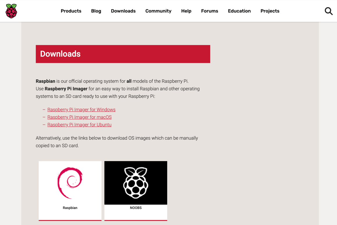
After you’ve downloaded the Raspberry Pi Imager, start the application. You’ll see a screen that allows you to select the operating system that you want to install along with the SD card you would like to format:
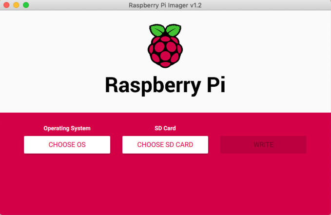
You’ll be given two options when first loading the application: Choose OS and Choose SD Card. Select Choose OS first.
Note: There’s a chance that Windows may prevent the Raspberry Pi Imager from starting because it’s an unrecognized application. If you receive a pop-up that says Windows protected your PC, then you can still run the application by clicking More info and selecting Run anyway.
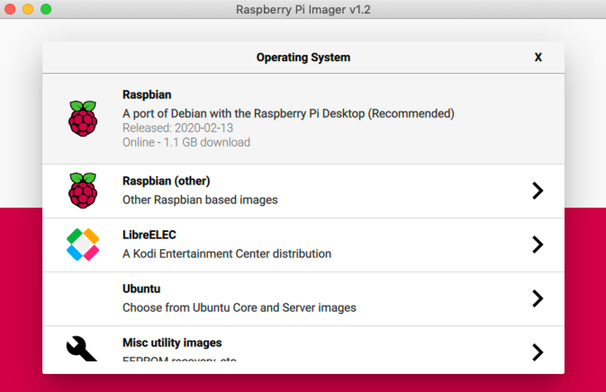
With the application running, click the Choose OS button and choose the first Raspbian option:
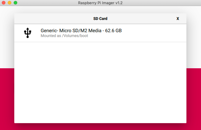
After selecting the Raspbian operating system, you need to select the SD card you’re going to use. Make sure your microSD card is inserted into your computer and click Choose SD Card, then select the SD card from the menu:
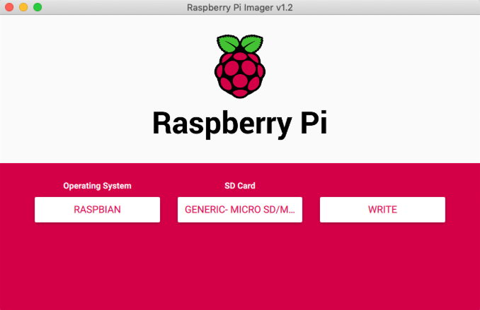
With the operating system and SD card selected, you can now click the Write button to begin formatting the SD card and installing the operating system onto the card. This process may take a few minutes to complete:
Once formatting and installation are complete, you should see a message that says the operating system has been written to the SD card:
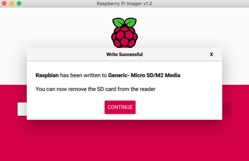
You can eject the SD card from your computer. Raspbian is now installed on your SD card, and you’re ready to start connecting hardware to the Raspberry Pi!
Option 2: Install Raspbian From NOOBS
If for some reason you can’t use the Raspberry Pi Imager, then you can download NOOBS (New Out Of the Box Software) and use it to install Raspbian on a microSD card. First, head to the NOOBS download page to download the latest version. Click Download ZIP underneath the first NOOBS option:

NOOBS will start downloading on your system.
Note: Make sure to download NOOBS and not NOOBS Lite.
Once the ZIP file has been downloaded, unzip the contents to a location on your computer. You’ll be copying these files onto the SD card shortly, but first you need to properly format the SD card.
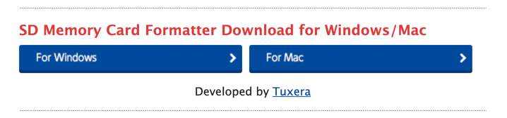
You’ll use the official SD Memory Card Formatter from the SD Association. Head to the SD Association website to download the formatter. Scroll to the bottom and download the SD formatter for either Windows or macOS:
Once the SD Memory Card Formatter is downloaded, you’re ready to format your SD card for use on the Raspberry Pi.
Note: Linux users can use fdisk to partition and format a microSD card to the required FAT32 disk format.
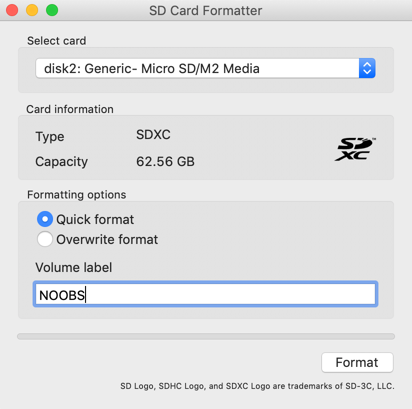
After downloading the SD formatter, open the application. To format the SD card, you’ll need to do the following:
- Insert the SD card into your computer.
- Select the SD card from the Select card dropdown menu.
- Click the Quick format option under Formatting options.
- Enter NOOBS into the Volume label text field.
Once the above items are complete, click Format:
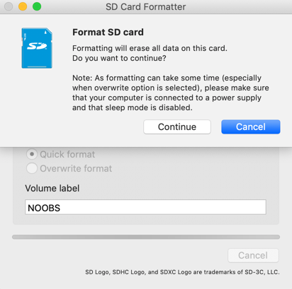
Before formatting the card, you’ll be asked to confirm the operation, as it will erase all data from the card. Click Continue to begin formatting the SD card. It may take a few minutes to finish formatting:
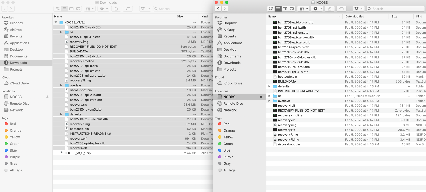
Once the formatting has completed, you’ll need to copy the NOOBS files that you unzipped earlier over to the SD card. Select all the files that you extracted earlier:
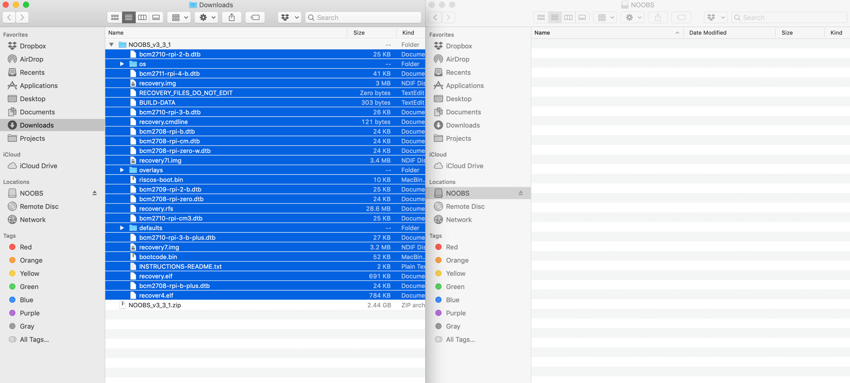
Drag them to the SD card:
Now that you’ve got NOOBS installed on your SD card, eject the card from your computer. You’re almost there! In the next section, you’ll do the final setup for your Raspberry Pi.
Final Setup
Now that you have the microSD card and required hardware ready, the final step is to connect everything together and configure the operating system. Let’s start off by connecting all the peripherals:
- Insert the microSD card into the card slot on the bottom of the Raspberry Pi.
- Connect the keyboard and mouse to any of the four USB ports.
- Connect a display to one of the HDMI ports using an HDMI cable specific to your Raspberry Pi model.
- Connect a power supply to the USB power port.
With the peripherals connected, go ahead and power on your Raspberry Pi to configure the operating system. If you installed Raspbian with the Raspberry Pi Imager, then there’s nothing else for you to do. You can skip down to the next section to complete the setup.
If you installed NOOBS on your SD card, then you’ll need to complete a couple more steps to install Raspbian on the SD card:
- First, power on the Raspberry Pi to load the NOOBS interface.
- Then, check the checkbox next to the Raspbian option in the list of software to install.
- Finally, click the Install button at the top left corner of the interface to begin installing Raspbian on the SD card.
Once the installation is complete, the Raspberry Pi will restart, and you’ll be booted into Raspbian to complete the setup wizard.
Setup Wizard
On first boot, Raspbian provides a setup wizard to help you configure your password, set your locale, select a Wi-Fi network, and update the operating system. Go ahead and complete these steps as instructed.
Once you’ve completed the steps, restart the operating system and you’ll be ready to begin programming Python on the Raspberry Pi!
Running Python on the Raspberry Pi
One of the best things about working with Python on the Raspberry Pi is that Python is a first-class citizen on the platform. The Raspberry Pi Foundation specifically selected Python as the main language because of its power, versatility, and ease of use. Python comes preinstalled on Raspbian, so you’ll be ready to start from the get-go.
You have many different options for writing Python on the Raspberry Pi. In this tutorial, you’ll look at two popular choices:
- Using the Mu editor
- Editing remotely over SSH
Let’s start by looking at using the Mu editor to write Python on the Raspberry Pi.
Using the Mu Editor
The Raspbian operating system comes with several preinstalled Python IDEs that you can use to write your programs. One of these IDEs is Mu. It can be found in the main menu:
Raspberry Pi Icon → Programming → Mu
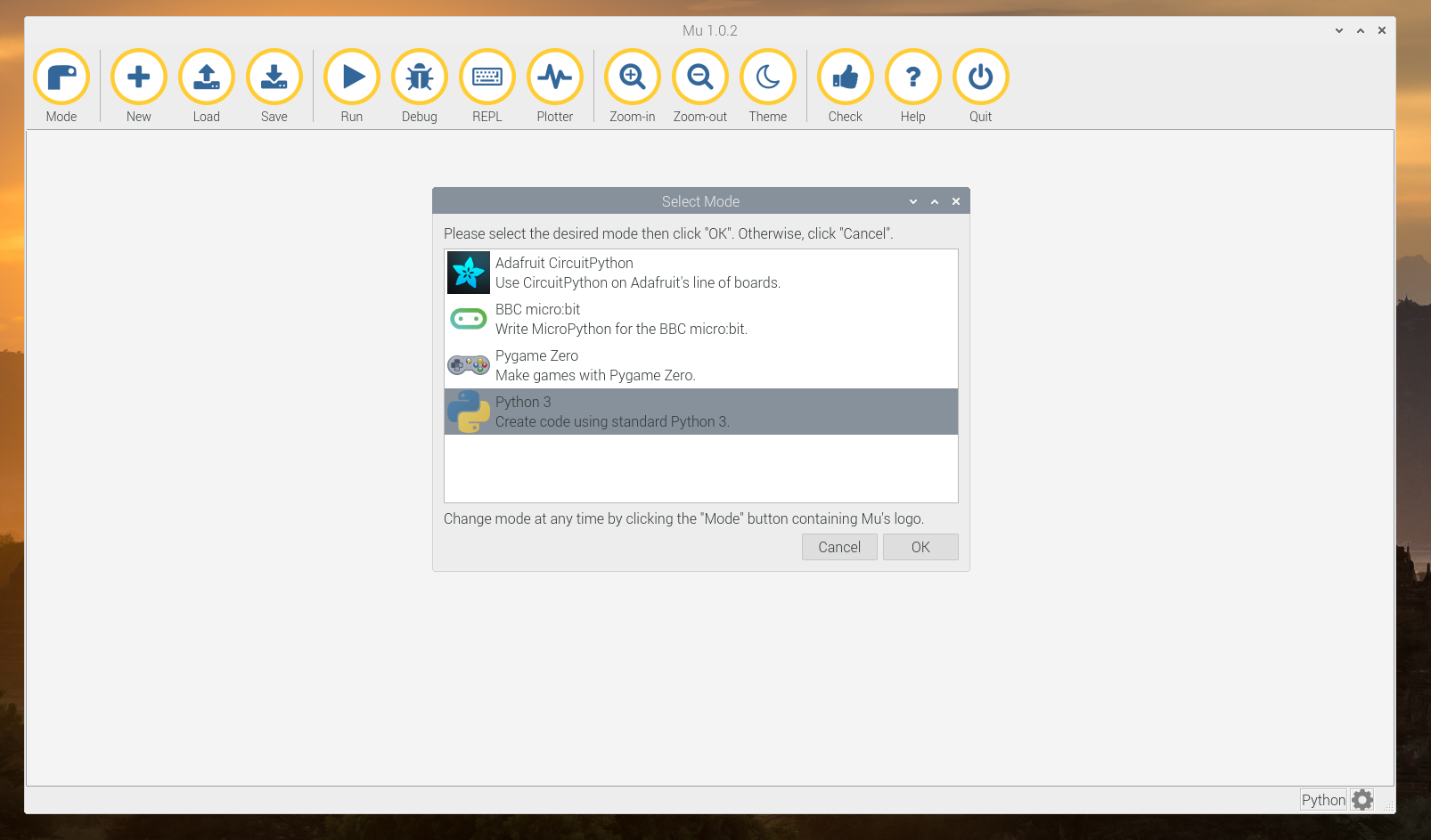
When you open Mu for the first time, you’ll be given the option to select the Python mode for the editor. For the code in this tutorial, you can select Python 3:
There’s a chance that Mu may not be preinstalled on your version of Raspbian. If Mu isn’t installed, then you can always install it by going to the following file location:
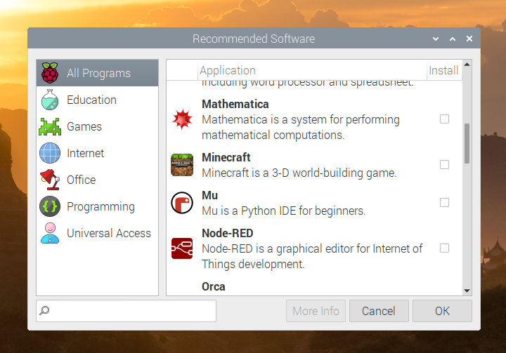
Raspberry Pi Icon → Preferences → Recommended Software
This will open up a dialogue containing recommended software for your Raspberry Pi. Check the box next to Mu and click OK to install it:
While Mu provides a great editor to get started with Python on the Raspberry Pi, you may want something more robust. In the next section, you’ll connect to your Raspberry Pi over SSH.
Editing Remotely Over SSH
Often you won’t want to spend the time hooking up a monitor, keyboard, and mouse to write Python on the Raspberry Pi. Luckily, Raspbian allows you to connect to the Raspberry Pi remotely over SSH. In this section, you’ll learn how to enable and use SSH to program Python on the Raspberry Pi.
Enable SSH
Before you can connect to the Raspberry Pi over SSH, you’ll need to enable SSH access inside the Raspberry Pi Preferences area. Enable SSH by going to the following file path:
Raspberry Pi Icon → Preferences → Raspberry Pi Configuration
Once the configuration appears, select the Interfaces tab and then enable the SSH option:
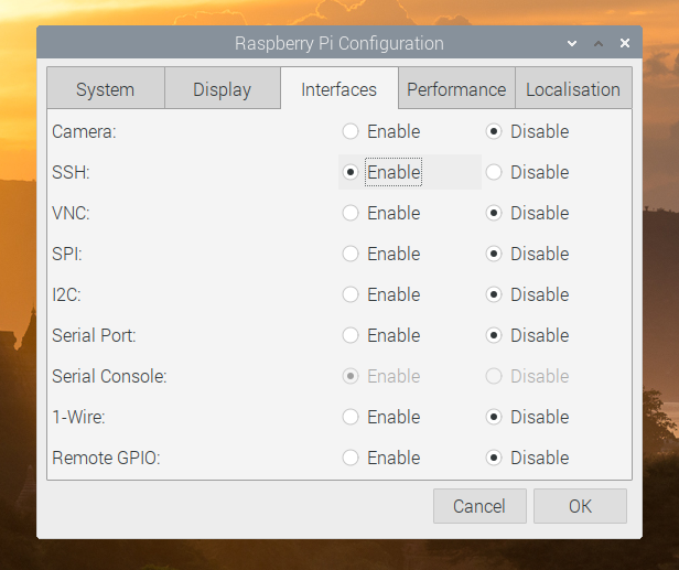
You’ve enabled SSH on the Raspberry Pi. Now you need to get the IP address for the Raspberry Pi so you can connect to it from another computer.
Determine the Raspberry Pi IP Address
To access the Raspberry Pi remotely, you need to determine the IP address of the Raspberry Pi on your local network. To determine the IP address, you need to access the Terminal application. You can access Terminal here:
Raspberry Pi Icon → Accessories → Terminal
Once Terminal is open, enter the following in the command prompt:
pi@raspberrypi:~ $ hostname -I
This will display the current IP address for your Raspberry Pi. With this IP address, you can now connect to your Raspberry Pi remotely.
Connect to the Raspberry Pi
Using the IP address for the Raspberry Pi, you can now SSH into it from another computer:
$ ssh pi@[IP ADDRESS]
You’ll be prompted to enter the password you created when running the setup wizard during the Raspbian installation. If you didn’t set a password, then the default password is raspberry. Enter the password, and after it connects you’ll see the Raspberry Pi command prompt:
pi@raspberrypi:~ $
Now that you know how to connect, you’re ready to start programming Python on the Raspberry Pi. You can get started right away using the Python REPL:
pi@raspberrypi:~ $ python3
Type in some Python to run it on the Raspberry Pi:
>>> print("Hello from your Raspberry Pi!")
Hello from your Raspberry Pi!
Awesome, you’re running Python on the Raspberry Pi!
Creating a python-projects Directory
Before you start building projects with Python on the Raspberry Pi, it’s a good idea to set up a dedicated directory for your code. The Raspberry Pi has a full file system with many different directories. Having a reserved place for your Python code will help keep everything organized and easy to find.
Let’s create a directory called python-projects where you can store Python code for your projects.
Using Mu
If you plan on using Mu to complete the projects in this tutorial, then you can use it now to create the python-projects directory. To create this directory, you’ll want to do the following:
- Open Mu by going to Raspberry Pi Icon → Programming → Mu.
- Click New in the menu bar to create an empty file.
- Click Save in the menu bar.
- Navigate to the
/home/pidirectory in the directory dropdown. - Click the Create New Folder icon in the top-right corner.
- Name this new directory
python-projectsand hit Enter. - Click Cancel to close.
You’ve created a dedicated directory for your Python code. Head down to the next section to learn about interacting with physical components in Python.
Over SSH
If you’d rather use SSH to access your Raspberry Pi, then you’ll use the command line to create the python-projects directory.
Note: Since you’ll be accessing the Raspberry Pi command line, you’ll need to use a command-line text editor to edit your project files.
Both nano and vim come preinstalled on Raspbian and can be used to edit the project files. You can also use VS Code to remotely edit files on the Raspberry Pi, but some setup is required.
Let’s create the python-projects directory. If you aren’t currently logged into the Raspberry Pi, then use the IP address of the Raspberry Pi to SSH into it from your computer:
$ ssh pi@[IP ADDRESS]
Once logged in, you’ll see the Raspberry Pi command prompt:
pi@raspberry:~ $
By default, when you SSH into the Raspberry Pi, you’ll start in the /home/pi directory. Confirm this now by running pwd:
pi@raspberry:~ $ pwd
/home/pi
If for some reason you’re not in the /home/pi directory, then switch to it using cd /home/pi:
pi@raspberry:~/Desktop $ cd /home/pi
pi@raspberry:~ $ pwd
/home/pi
Now in the /home/pi directory, create a new python-projects directory:
pi@raspberry:~ $ mkdir python-projects
With the python-projects directory created, use cd python-projects to go into the directory:
pi@raspberry:~ $ cd python-projects
pi@raspberry:~/python-projects $
Great! You’re ready to start coding your first circuits using Python on the Raspberry Pi.
Interacting With Physical Components
In this section, you’ll learn how to interact with different physical components using Python on the Raspberry Pi.
You’ll be using the gpiozero library that comes preinstalled on Raspbian. It provides an easy-to-use interface to interact with a variety of GPIO devices connected to the Raspberry Pi.
Electronic Components
Before programming on the Raspberry Pi, you’ll need a few electronic components to build the projects in the upcoming sections. You should be able to find each of the items below on Amazon or at your local electronics store.
Breadboard
A breadboard is an essential tool when building circuits. It allows you to quickly prototype your circuit without having to solder components together.
Breadboards follow a general layout. On the right and left sides, two rails run the length of the breadboard. Every hole on these rails is connected. Generally, these are designated positive (voltage, or VCC) and negative (ground, or GND).
On most breadboards, the positive rail is marked with a positive sign (+) and will have a red line running next to it. The negative rail is marked with a negative sign (-) and has a blue line running next to it.
On the interior of the board, component rails run perpendicular to the positive and negative rails on the sides of the breadboard. Each of these rails contains holes for placing components.
All holes in a single rail are connected. In the middle is a gutter separating the two sides of the breadboard. Rails on opposite sides of the gutter are not connected.
This is illustrated in the following diagram:

In the diagram above, three colors are used to mark the different types of breadboard rails:
- Red: Positive rail
- Black: Negative rail
- Blue: Component rails
Later in this tutorial, you’ll use these different rails to build full circuits that connect to the Raspberry Pi.
Jumper Wires
Jumper wires allow you to prototype the connections of your circuit without having to solder paths between GPIO pins and components. They come in three different types:
It would be good to have at least ten to twenty of each type when you’re building your Raspberry Pi projects in Python.
Other Components
Along with the breadboard and jumper wires, the projects in this tutorial will use the following components:
- Light-emitting diodes (LEDs)
- Tactile button
- 330 Ω resistor
- Active piezo buzzer
- Passive infrared motion sensor
With the required components in hand, let’s take a look at how you can connect them to the Raspberry Pi using the GPIO pins.
GPIO Pins
The Raspberry Pi features forty GPIO pins along the top edge of the board. You can use these GPIO pins to connect the Raspberry Pi to external components.
The pin layout below shows the different types of pins and their locations. This layout is based on an overhead view of the pins with the Raspberry Pi’s USB ports facing you:
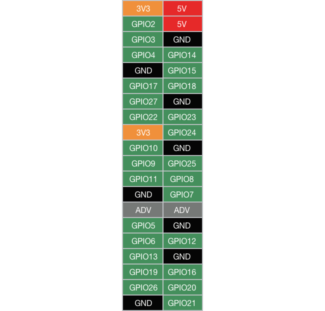
The Raspberry Pi features five different types of pins:
- GPIO: These are general-purpose pins that can be used for input or output.
- 3V3: These pins supply a 3.3 V power source for components. 3.3 V is also the internal voltage that all GPIO pins supply.
- 5V: These pins supply a 5 V power source, the same as the USB power input that powers the Raspberry Pi. Some components, such as the passive infrared motion sensor, require 5 V.
- GND: These pins provide a ground connection for circuits.
- ADV: These special-purpose pins are advanced and not covered in this tutorial.
In the next section, you’ll use these different pin types to set up your first component, a tactile button.
Tactile Button
For your first circuit, you’re going to connect a tactile button to the Raspberry Pi. A tactile button is an electronic switch that, when pressed, closes a circuit. When a circuit is closed, the Raspberry Pi will register an ON signal. You can use this ON signal to trigger different actions.
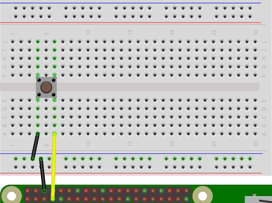
In this project, you’ll use a tactile button to run different Python functions based on the state of the button. Let’s start by wiring the button to the Raspberry Pi:
- Connect a female-to-male jumper wire from the Raspberry Pi’s GND pin to the negative rail of the breadboard.
- Place a tactile button across the gutter in the middle of the breadboard.
- Connect a male-to-male jumper wire from the negative rail of the breadboard to the row where the button’s bottom-left leg is placed.
- Connect a female-to-male jumper wire from the Raspberry Pi’s GPIO4 pin to the breadboard row where the button’s bottom-right leg is placed.
You can confirm your wiring with the diagram below:
Now that you’ve got your circuit wired up, let’s write the Python code to read input from the button.
Note: If you’re having trouble finding a specific pin, then make sure to reference the GPIO pin layout image when building your circuits. You can also purchase a breakout board for easy breadboarding.
Inside the python-projects directory that you created earlier, save a new file called button.py. If you’re using SSH to access your Raspberry Pi, then create the file like this:
pi@raspberrypi:~/ cd python-projects
pi@raspberrypi:~/python-projects $ touch button.py
If you’re using Mu, then create the file with the following steps:
- Click the New menu item.
- Click Save.
- Navigate to the
/home/pi/python-projectsdirectory. - Save the file as
button.py.
With the file created, you’re ready to start coding. Start by importing the Button class from the gpiozero module. You’ll also need to import pause from the signal module. You’ll look at why you need pause later:
from gpiozero import Button
from signal import pause
Create an instance of the Button class and pass the pin number as a parameter. In this case, you’re using the GPIO4 pin, so you’ll pass in 4 as the parameter:
button = Button(4)
Next, define functions that will be called for the different button events that are available on a Button instance:
def button_pressed():
    print("Button was pressed")

def button_held():
    print("Button was held")

def button_released():
    print("Button was released")
The Button class has three event properties: .when_pressed, .when_held, and .when_released. These properties can be used to hook up different event functions.
While the .when_pressed and .when_released properties are self-explanatory, .when_held requires a short explanation. If a function is set to the .when_held property, then it will only be called if the button is pressed and held for a certain amount of time.
The hold time for .when_held is determined by the .hold_time property on the Button instance. The default for .hold_time is one second. You can override this by passing a float value when creating a Button instance:
button = Button(4, hold_time=2.5)
button.when_held = button_held
This will create a Button instance that will wait two and a half seconds after the button is pressed and held before calling the button_held() function.
Now that you know about the different event properties on Button, set each of these to their respective functions that you defined earlier:
button.when_pressed = button_pressed
button.when_held = button_held
button.when_released = button_released
Great! You’ve got your button events set up. The last thing you need to do is to call pause() at the end of the file. Calling pause() is required to keep the program listening for the different events. If this wasn’t present, then the program would run once and exit.
Your final program should look like this:
from gpiozero import Button
from signal import pause

button = Button(4)

def button_pressed():
    print("Button was pressed")

def button_held():
    print("Button was held")

def button_released():
    print("Button was released")

button.when_pressed = button_pressed
button.when_held = button_held
button.when_released = button_released

pause()
With the wiring complete and the code all set up, you’re ready to try out your first circuit. Inside of the python-projects directory, run the program:
pi@raspberrypi:~/python-projects $ python3 button.py
If you’re using Mu, first make sure the file is saved, then click Run to start the program.
The program is now running and listening for events. Press the button, and you should see the following in the console:
Button was pressed
Press and hold the button for at least one second, and you should see the following output:
Button was held
Finally, when you release the button you should see the following:
Button was released
Awesome! You’ve just wired and coded your first circuit using Python on the Raspberry Pi.
Since you used pause() in your code, you’ll need to manually stop the program. If you’re running the program in Mu, then you can click Stop to quit the program. If you’re running this from the command line, then you can stop the program with Ctrl+C.
With this first circuit under your belt, you’re ready to start controlling some other components.
LED
For your next circuit, you’ll use Python to blink an LED on and off every second. LED stands for light-emitting diode, and these components produce light when a current is applied. You’ll find that they’re used everywhere in electronics.
Every LED has two legs. The longer leg is the positive leg, or anode. The electrical current enters the LED through this leg. The shorter leg is the negative leg, or cathode. The current exits the LED through this leg.
Current can only flow one direction through an LED, so make sure you’re connecting jumper wires to the proper leg of the LED.
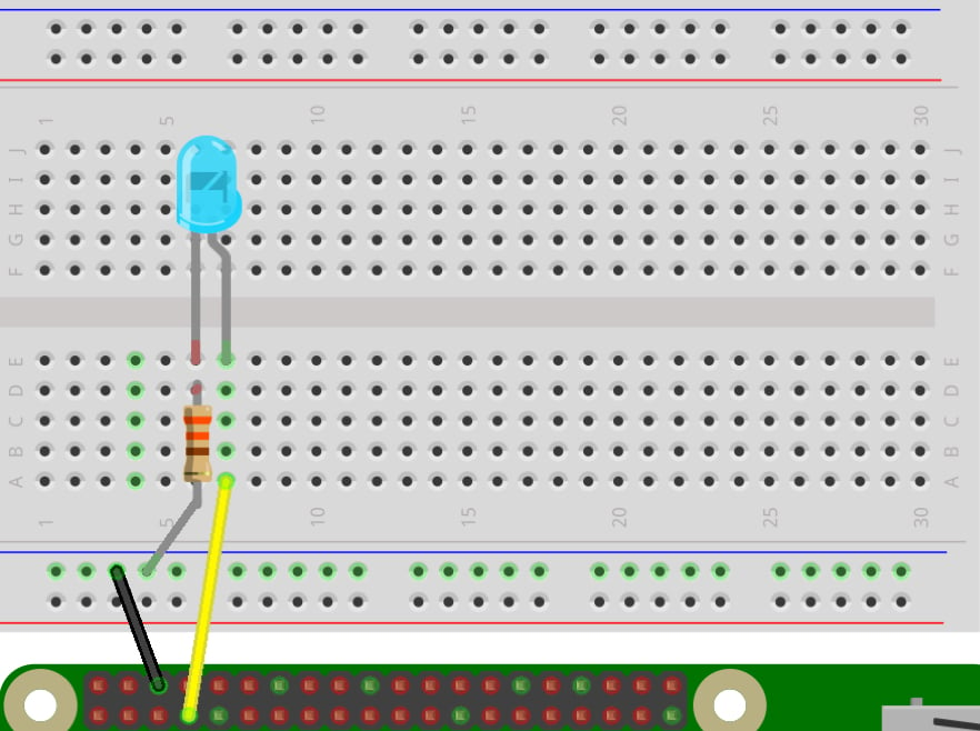
Here are the steps you’ll need to take to wire this circuit:
-
Connect a female-to-male jumper wire from the Raspberry Pi’s GND pin to the negative rail of the breadboard.
-
Place an LED into two holes on the breadboard that are next to each other but not in the same row.
-
Place the longer, positive leg of the LED into the hole on the right side.
-
Place the shorter, negative leg of the LED into the hole on the left side.
-
Place one end of a 330 Ω resistor into a hole in the same breadboard row as the negative leg of the LED.
-
Place the other end of the resistor into the negative rail of the breadboard
-
Connect a female-to-male jumper wire from the Raspberry Pi’s GPIO4 pin to a hole in the same breadboard row as the positive leg of the LED.
You can confirm your wiring with the diagram below:
If the wiring looks good, then you’re ready to write some Python to get the LED blinking. Start by creating a file for this circuit inside of the python-projects directory. Call this file led.py:
pi@raspberrypi:~/python-projects $ touch led.py
In this code, you’ll create an instance of the LED class and call its .blink() method to make the LED blink on and off. The .blink() method has a default timeout of one second. The LED will continue to blink on and off every second until the program is exited.
Start by importing LED from the gpiozero module and pause from the signal module:
from gpiozero import LED
from signal import pause
Next, create an instance of LED called led. Set the GPIO pin to 4:
led = LED(4)
Call the .blink() method on led:
led.blink()
Finally, add a call to pause() to make sure the program doesn’t exit:
pause()
Your complete program should look like this:
from gpiozero import LED
from signal import pause

led = LED(4)
led.blink()

pause()
Save the file and run it to see the LED blink on and off:
pi@raspberrypi:~/python-projects $ python3 led.py
The LED should now be blinking on and off every second. When you’re done admiring your Python code in action, stop the program with Ctrl+C or Stop in Mu.
Now you know how to control an LED with Python on the Raspberry Pi. For the next circuit, you’ll be using Python to produce sound from the Raspberry Pi.
Buzzer
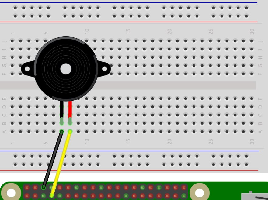
In this circuit, you’ll be wiring an active piezo buzzer to the Raspberry Pi. A piezo buzzer emits a tone when current is applied. Using this component, your Raspberry Pi will be able to generate sound.
Like LEDs, a buzzer has a positive and negative leg. The positive leg of the buzzer will either be longer than the negative leg or there will be a positive sign (+) on the top of the buzzer showing which leg is the positive leg.
Let’s go ahead and wire up the buzzer:
-
Place a buzzer on the breadboard, noting the placement of the buzzer’s positive leg.
-
Connect a female-to-male jumper wire from the Raspberry Pi’s GND pin to a hole in the same breadboard row as the negative leg of the buzzer.
-
Connect a female-to-male jumper wire from the Raspberry Pi’s GPIO4 pin to a hole in the same breadboard row as the positive leg of the buzzer.
Confirm your wiring against the diagram below:
With the wiring set up, let’s move on to the code. Create a file for this circuit inside the python-projects directory. Call this file buzzer.py:
pi@raspberrypi:~/python-projects $ touch buzzer.py
In this code, you’ll create an instance of the Buzzer class and call it’s .beep() method to make the buzzer beep on and off. The .beep() method’s first two parameters are on_time and off_time. These parameters take a float value to set how long the buzzer should beep on and off. The default value for both is one second.
Start by importing Buzzer from the gpiozero module and pause from the signal module:
from gpiozero import Buzzer
from signal import pause
Next, create an instance of Buzzer called buzzer. Set the GPIO pin to 4:
buzzer = Buzzer(4)
Call the .beep() method on buzzer. Set the on_time and off_time parameters to 0.5. This will make the buzzer beep every half second:
buzzer.beep(0.5, 0.5)
Finally, add a call to pause() to make sure the program doesn’t exit:
pause()
Your complete program should look like this:
from gpiozero import Buzzer
from signal import pause

buzzer = Buzzer(4)
buzzer.beep(0.5, 0.5)

pause()
Save the file and run it to hear the buzzer beep on and off every half second:
pi@raspberrypi:~/python-projects $ python3 buzzer.py
You should hear the buzzer sound on and off until you stop the program with Ctrl+C or Stop in Mu.
Note: If you’re using Mu, then there’s a chance that when you stop the program the tone will continue. To stop the sound, remove the GND wire to break the circuit.
You may also need to restart Mu if the tone continues when you reconnect the GND wire.
Great! So far you’ve learned how to control three different types of electronic components with Python on the Raspberry Pi. For the next circuit, let’s take a look at a slightly more complex component.
Motion Sensor
In this circuit, you’ll be connecting a passive infrared (PIR) motion sensor to the Raspberry Pi. A passive infrared motion sensor detects any motion in its field of vision and sends a signal back to the Raspberry Pi.
Adjusting the Sensor
When using a motion sensor, you may need to adjust how sensitive it is to motion and how long it will send out a signal after motion is detected.
You can make adjustments using two dials on the side of the sensor. You’ll know which dials they are because they’ll have a cross-shaped indentation in the center, which can be adjusted with a Phillips-head screwdriver.
The image below shows these dials on the side of the motion sensor:
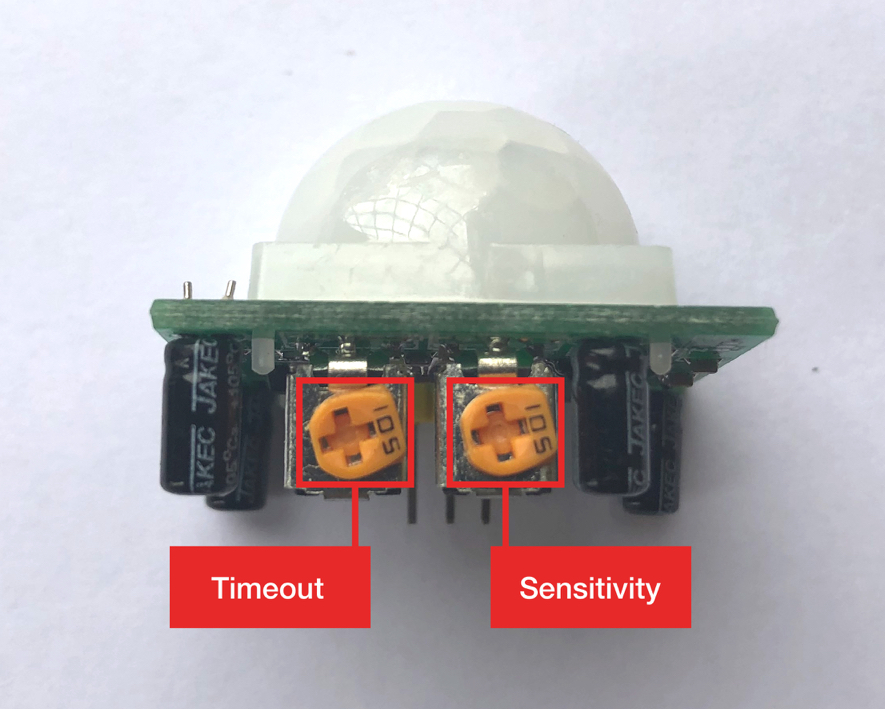
As the image shows, the left dial sets the signal timeout and the right dial sets the sensor sensitivity. You can turn these dials clockwise or counterclockwise to adjust them:
- Clockwise increases the timeout and sensitivity.
- Counterclockwise decreases the timeout and sensitivity.
You can adjust these based on your project needs, but for this tutorial turn both dials counterclockwise all the way. This will set them to their lowest values.
Note: Occasionally, a motion sensor and a Raspberry Pi 3 will not work together correctly. This results in occasional false positives from the sensor.
If you’re using a Raspberry Pi 3, then make sure to move the sensor as far from the Raspberry Pi as possible.
Once you’ve adjusted the motion sensor, you’re ready to set up the wiring. The motion sensor’s design doesn’t allow it to easily connect to a breadboard. You’ll need to connect the Raspberry Pi’s GPIO pins directly to the pins on the motion sensor with jumper wires.
The image below shows the placement of the pins on the underside of the motion sensor:
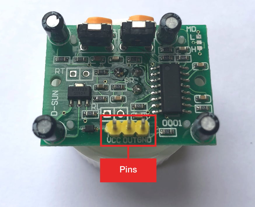
You can see there are three pins:
- VCC for voltage
- OUT for communicating with the Raspberry Pi
- GND for ground
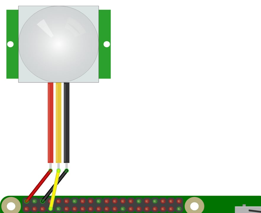
Using these pins, you need to take the following steps:
- Connect a female-to-female jumper wire from the Raspberry Pi’s 5V pin to the sensor’s VCC pin.
- Connect a female-to-female jumper wire from the Raspberry Pi’s GPIO4 pin to the sensor’s OUT pin.
- Connect a female-to-female jumper wire from the Raspberry Pi’s GND pin to the sensor’s GND pin.
Now confirm the wiring with the diagram below:
With the motion sensor adjusted and wired to the Raspberry PI, let’s take a look at the Python code for detecting motion. Start by creating a file for this circuit inside the python-projects directory. Call this file pir.py:
pi@raspberrypi:~/python-projects $ touch pir.py
The code for this circuit is going to be similar to the button circuit you made previously. You’ll create an instance of the MotionSensor class and pass in the GPIO pin number 4 as the parameter. You’ll then define two functions and set them to the .when_motion and .when_no_motion properties on the MotionSensor instance.
Let’s take a look at the code:
from gpiozero import MotionSensor
from signal import pause

motion_sensor = MotionSensor(4)

def motion():
    print("Motion detected")

def no_motion():
    print("Motion stopped")

print("Readying sensor...")
motion_sensor.wait_for_no_motion()
print("Sensor ready")

motion_sensor.when_motion = motion
motion_sensor.when_no_motion = no_motion

pause()
motion() is set to the .when_motion property and is called when the sensor detects motion. no_motion() is set to the .when_no_motion property and is called when motion has stopped for a certain period. This time is determined by the timeout dial on the side of the sensor.
You’ll notice that before the .when_motion and .when_no_motion properties are set, there is a call to .wait_for_no_motion() on the MotionSensor instance. This method will pause the execution of the code until the motion sensor no longer detects any motion. This is so that the sensor will ignore any initial motion that may occur as the program is starting up.
Note: Motion sensors can sometimes be too sensitive or not sensitive enough. If you see inconsistent results in the console when running the code above, then make sure to check that everything is wired correctly. You may also need to adjust the sensitivity dial on your sensor.
If your results are delayed in the console, then try adjusting down the .threshold property on the MotionSensor instance. The default value is 0.5:
pir = MotionSensor(4, threshold=0.2)
This will decrease the amount of motion required to make the sensor active. For more information on the MotionSensor class, see the gpiozero documentation.
Save the code and run it to try out your motion detection circuit:
pi@raspberrypi:~/python-projects $ python3 pir.py
Readying sensor...
Sensor ready
Wave your hand in front of the sensor. When motion is first detected, motion() is called and the following is displayed in the console:
Motion detected
Now stop waving your hand in front of the sensor. After a few seconds, the following will be displayed:
Motion stopped
Great! You can now detect motion with your Raspberry Pi. Once you’re done waving at your Raspberry Pi, go ahead and hit Ctrl+C in the command line or press Stop in Mu to terminate the program.
With this final circuit, you’ve learned how to use Python on the Raspberry Pi to control four different components. In the next section, you’ll tie all of this together in a full project.
Building a Motion-Activated Alarm System
Now that you’ve had the chance to connect the Raspberry Pi to a variety of inputs and outputs, you’re going to create a project that uses what you’ve learned so far.
In this project, you’ll build a motion-activated alarm system that will flash an LED and sound an alarm when it detects motion in a room. On top of this, you’ll use Python to save a timestamp to a CSV file detailing each time motion occurs.
Wiring
Here are the steps to complete the wiring:
-
Connect female-to-male jumper wires from the Raspberry Pi’s 5V and GND pins to the positive and negative rails on the side of the breadboard.
-
Place an LED on the breadboard and connect the Raspberry Pi’s GPIO14 pin to the LED with a female-to-male jumper wire.
-
Connect the LED’s negative leg to the breadboard’s negative rail through a 330 Ω resistor.
-
Place a buzzer on the breadboard and connect the Raspberry Pi’s GPIO15 pin to the buzzer with a female-to-male jumper wire.
-
Connect the buzzer’s negative leg to the breadboard’s negative rail with a male-to-male jumper wire.
-
Connect a female-to-male jumper wire from the breadboard’s positive rail to the sensor’s VCC pin.
-
Connect a female-to-female jumper wire from the Raspberry Pi’s GPIO4 pin to the sensor’s OUT pin.
-
Connect a female-to-male jumper wire from the breadboard’s negative rail to the sensor’s GND pin.
Confirm the wiring against the diagram below:
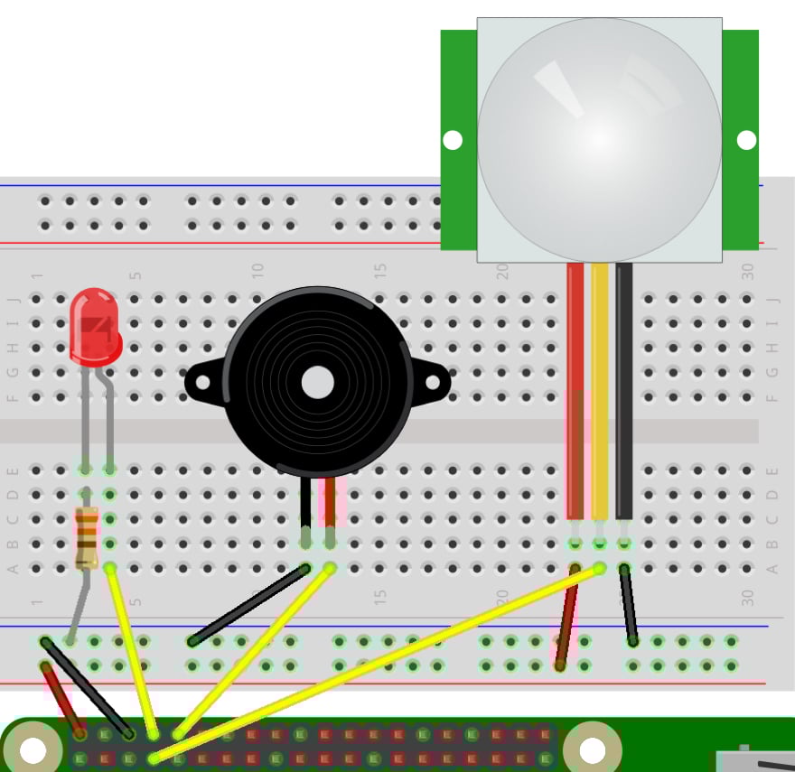
Okay, now that you have the circuit wired up, let’s dig into the Python code to set up your motion-activated alarm system.
Code
As usual, start by creating a file for this project inside the python-projects directory. For this project, call this file motion_detector.py:
pi@raspberrypi:~/python-projects $ touch motion_detector.py
The first thing you want to do is import the csv module so you can save a timestamp when motion is detected. Also, import Path from the pathlib module so you can reference your CSV file:
import csv
from pathlib import Path
Next, import datetime from the datetime module so you can create a timestamp of the motion event:
from datetime import datetime
Finally, import the required component classes from gpiozero as well as pause from the signal module:
from gpiozero import LED, Buzzer, MotionSensor
from signal import pause
With the imports ready, you can set up the three electronic components you’ll be using. Create instances of the LED, Buzzer, and MotionSensor classes. For each of these, pass in their pin numbers as parameters:
led = LED(14)
buzzer = Buzzer(15)
motion_sensor = MotionSensor(4)
Next, define the location of a CSV file that will store a timestamp each time motion is detected. You’ll call it detected_motion.csv. Create a dictionary to hold the timestamp values that will be written to the CSV:
output_csv_path = Path("detected_motion.csv")
motion = {
    "start_time": None,
    "end_time": None,
}
Create a method that saves the timestamp data to a CSV file. When the file is first created, a header row is added:
def write_to_csv():
    first_write = not output_csv_path.is_file()

    with open(output_csv_path, "a") as file:
        field_names = motion.keys()
        writer = csv.DictWriter(file, field_names)
        if first_write:
            writer.writeheader()
        writer.writerow(motion)
Define a start_motion() function. This function will have several behaviors:
- Start blinking the
ledon and off every half second - Make the
buzzerbeep - Save the
start_timetimestamp to themotiondictionary
Add a call to print() so you can watch the events occur while the program is running:
def start_motion():
    led.blink(0.5, 0.5)
    buzzer.beep(0.5, 0.5)
    motion["start_time"] = datetime.now()
    print("motion detected")
Then define an end_motion() function that will have the following behaviors:
- Turn off the
ledandbuzzer - Save the
end_timetimestamp - Call
write_to_csv()to save the motion data to the CSV file - Reset the
motiondictionary
You’ll also check that a motion["start_time"] value exists before running any of the other code. You only want to write to the CSV if a start_time timestamp was recorded:
def end_motion():
    if motion["start_time"]:
        led.off()
        buzzer.off()
        motion["end_time"] = datetime.now()
        write_to_csv()
        motion["start_time"] = None
        motion["end_time"] = None
    print("motion ended")
Add a call to .wait_for_no_motion() so that any initial motion is ignored:
print("Readying sensor...")
motion_sensor.wait_for_no_motion()
print("Sensor ready")
Set the .when_motion and .when_no_motion properties on the MotionSensor instance:
motion_sensor.when_motion = start_motion
motion_sensor.when_no_motion = end_motion
Finally, end the code with a call to pause() to keep the program running. The full Python code should look like this:
import csv
from pathlib import Path
from datetime import datetime
from gpiozero import LED, Buzzer, MotionSensor
from signal import pause

led = LED(14)
buzzer = Buzzer(15)
motion_sensor = MotionSensor(4)

output_csv_path = Path("detected_motion.csv")
motion = {
    "start_time": None,
    "end_time": None,
}

def write_to_csv():
    first_write = not output_csv_path.is_file()

    with open(output_csv_path, "a") as file:
        field_names = motion.keys()
        writer = csv.DictWriter(file, field_names)
        if first_write:
            writer.writeheader()
        writer.writerow(motion)

def start_motion():
    led.blink(0.5, 0.5)
    buzzer.beep(0.5, 0.5)
    motion["start_time"] = datetime.now()
    print("motion detected")

def end_motion():
    if motion["start_time"]:
        led.off()
        buzzer.off()
        motion["end_time"] = datetime.now()
        write_to_csv()
        motion["start_time"] = None
        motion["end_time"] = None
    print("motion ended")

print("Readying sensor...")
motion_sensor.wait_for_no_motion()
print("Sensor ready")

motion_sensor.when_motion = start_motion
motion_sensor.when_no_motion = end_motion

pause()
Save the file and run it to test out your new motion detector alarm:
pi@raspberrypi:~/python-projects $ python3 motion_detector.py
Readying sensor...
Sensor ready
Now if you wave your hand in front of the motion detector, then the buzzer should start beeping and the LED should flash. If you stop moving for a few seconds, then the alarm should stop. In the console you should see the following:
pi@raspberrypi:~/python-projects $ python3 motion_detector.py
Readying sensor...
Sensor ready
motion detected
motion ended
motion detected
motion ended
...
Go ahead and stop the program with Stop in Mu or Ctrl+C. Let’s check out the CSV file that was generated:
pi@raspberrypi:~/python-projects $ cat detected_motion.csv
start_time,end_time
2020-04-21 10:53:07.052609,2020-04-21 10:53:13.966061
2020-04-21 10:56:56.477952,2020-04-21 10:57:03.490855
2020-04-21 10:57:04.693970,2020-04-21 10:57:12.007095
As you can see, the timestamps for the motion’s start_time and end_time have been added to the CSV file.
Congratulations! You’ve created a non-trivial electronics project with Python on the Raspberry Pi.
Next Steps
You don’t have to stop here. There are many ways you could improve this project by leveraging the capabilities of Python on the Raspberry Pi.
Here are some ways to level up this project:
-
Connect the Raspberry Pi Camera Module and have it take a photo whenever motion is detected.
-
Connect a speaker to the Raspberry Pi and use PyGame to play a sound file to intimidate an intruder.
-
Add a button to the circuit to allow a user to manually toggle motion detection on or off.
There are many ways to upgrade this project. Let us know what you come up with!
Conclusion
The Raspberry Pi is an amazing computing device that just keeps getting better. It’s packed with features that make it the go-to device for physical computing.
In this tutorial, you’ve learned how to:
- Set up a Raspberry Pi and run Python code on it
- Read input from sensors
- Send output to electronic components
- Build a cool project using Python on the Raspberry Pi
Python is the perfect complement to the Raspberry Pi, and with the skills you’ve learned you’re ready to tackle cool and innovative physical computing projects. We can’t wait to hear what you build!